Choosing the wrong BMS is one of the most common causes of premature failure in LiFePO4 battery packs — and one of the easiest problems to avoid. This guide walks you through exactly what a LiFePO4 BMS does, which specifications matter for your application, and how to avoid the installation mistakes that send most support tickets our way.
About LiFePO4 BMS
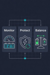
A LiFePO4 BMS (Battery Management System) is the electronic brain between your battery cells and the rest of your system. It does three things:
- Monitors every cell individually — tracking voltage, temperature, and state of charge in real time.
- Protects the pack — cutting off charge or discharge the moment a cell goes outside its safe operating window.
- Balances the cells — equalising the charge level across all cells in the pack so the weakest cell does not drag down the whole system.
Without a BMS, individual cells drift apart over time. The cell that charges fastest will hit its over-voltage limit first and cap the whole pack's usable capacity. The one that discharges fastest will drop below its safe threshold and age at an accelerated rate. A properly specified BMS prevents both.
LiFePO4 BMS: How to Choose the Right Battery Management System for Your Pack
Choosing the wrong BMS is one of the most common causes of premature failure in LiFePO4 battery packs — and one of the easiest problems to avoid. This guide walks you through exactly what a LiFePO4 BMS does, which specifications matter for your application, and how to avoid the installation mistakes that send most support tickets our way.
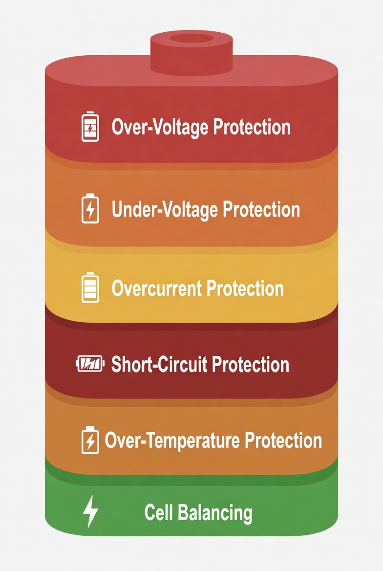
Core Protection Functions — What Each One Does
Every reliable LiFePO4 BMS covers these six protection layers as standard. If a BMS you are evaluating is missing any of them, move on.
| Protection | What Triggers It | Why It Matters |
| Over-Voltage Protection (OVP) | Cell voltage rises above ~3.65 V during charging | Prevents overcharging, electrolyte breakdown, and capacity fade |
| Under-Voltage Protection (UVP) | Cell voltage falls below ~2.50 V during discharge | Prevents deep discharge that causes irreversible cell damage |
| Overcurrent Protection (OCP) | Discharge current exceeds the rated limit | Protects FETs, busbars, and cell tabs from thermal damage |
| Short-Circuit Protection (SCP) | A sudden current spike is detected (microsecond response) | Shuts down the pack before a hard fault can cause fire or venting |
| Over-Temperature Protection (OTP) | Cell or MOSFET temperature exceeds threshold | Stops charge or discharge before heat causes accelerated degradation |
| Cell Balancing | Voltage spread detected between cells | Equalises state-of-charge so the full pack capacity is usable |
Note: Exact trigger thresholds (e.g., 3.65 V for OVP) are configured during BMS calibration and vary between models. Always check the datasheet for the specific SKU you are ordering.
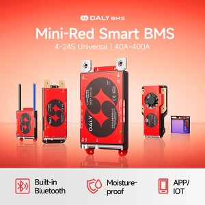
Daly BMS LiFePO4 Product Range — Technical Overview
The Daly BMS LiFePO4 family covers a wide range of configurations from compact 12V DIY packs through to 48V+ industrial and energy storage systems. Key parameters by model group:
| Parameter | Range / Options | Notes |
| Battery Chemistry | LiFePO4 (LFP) | Dedicated LFP voltage calibration; separate models for Li-ion / LTO |
| Series Cell Count (S) | 4S · 8S · 12S · 16S · 20S · 24S | Covers 12V · 24V · 36V · 48V · 60V · 72V nominal pack voltages |
| Continuous Current Rating | 20A — 200A (model dependent) | Always size at ≥110% of your maximum continuous load current |
| Balancing Method | Passive balancing (standard) / Active balancing (upgrade) | Active balancing preferred for packs above 100Ah or frequent partial cycling |
| Communication Interface | UART · RS485 · Bluetooth (Smart BMS models) | Required if your inverter/charger needs real-time SOC or cell data |
| Housing Options | Standard / Conformal coated / IP67 on request | Outdoor, marine, and industrial environments require higher IP ratings |
| OEM / ODM | Available | Custom firmware, labelling, housing, and protocol integration supported |
For model-specific datasheets and current specification documents, visit dalybms.com or contact our technical team directly.
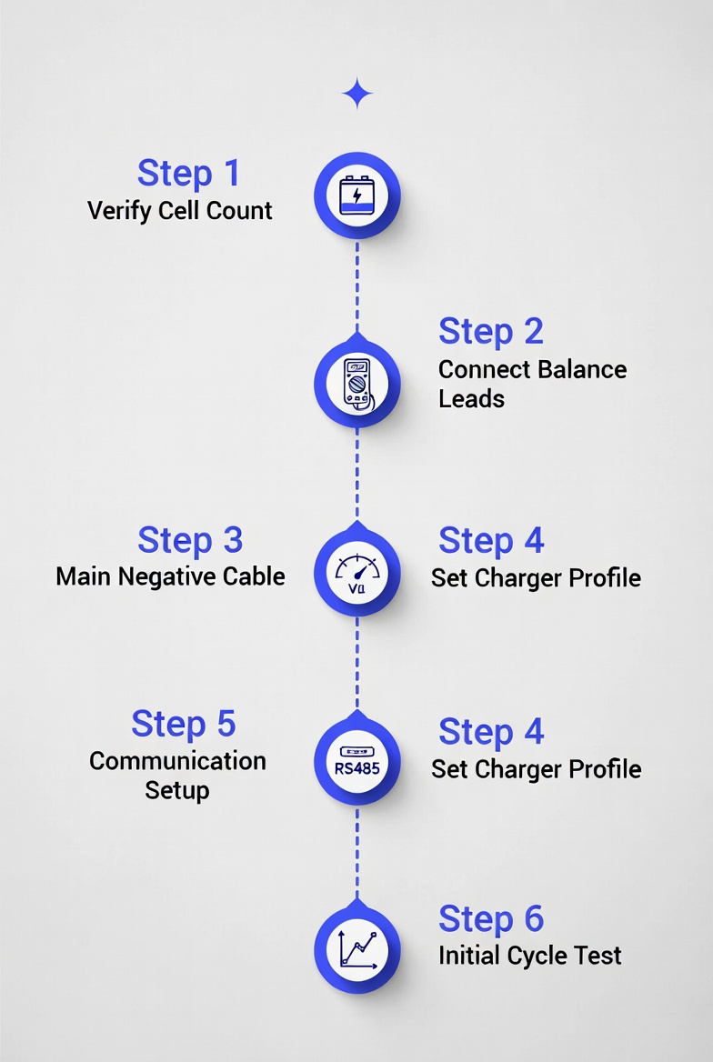
How to Select the Right LiFePO4 BMS — 5-Step Process
Work through these five steps in order. Skipping any one of them is how mismatches happen.
Step 1 — Count Your Cells in Series (S Count)
The S count determines the BMS model. Each LiFePO4 cell has a nominal voltage of 3.2 V. Add them up:
- 4S = 12.8 V nominal → standard 12V system
- 8S = 25.6 V nominal → standard 24V system
- 16S = 51.2 V nominal → standard 48V system
- 24S = 76.8 V nominal → standard 72V system
A BMS rated for the wrong S count will either fail to read cell voltages correctly or apply incorrect protection thresholds. There is no workaround — S count must match exactly.
Step 2 — Determine Your Continuous Current Requirement
Add up the nameplate current of all loads that can run at the same time. Apply a 10–20% margin on top for surge. Select the next available BMS current rating above that total. For example: a 2,000W inverter on a 24V system draws approximately 83A at full load — a 100A BMS is the correct minimum choice.
Do not size on average load. The BMS must handle the worst-case simultaneous load without tripping.
Step 3 — Decide Between Passive and Active Balancing
Passive balancing burns off the excess charge in high-SOC cells through a resistor. It works, but it is slow and generates heat. Active balancing transfers charge from high-SOC cells to low-SOC cells using inductors or capacitors — faster, more energy-efficient, and better for large packs.
If your pack is above 100Ah, is frequently partially cycled (solar applications), or is in an enclosed space where heat is a concern, active balancing is the better investment.
Step 4 — Check What Communication Your System Needs
If your inverter, solar charge controller, or monitoring platform needs real-time battery data — state of charge, cell voltages, temperature, alarm flags — you need a BMS with a matching interface. RS485 is the standard for most 48V inverter systems. Bluetooth covers DIY and mobile monitoring. Some inverters require CAN bus or a proprietary protocol. Confirm compatibility before ordering.
Step 5 — Verify the Environmental Rating
A BMS installed indoors in a dry enclosure needs no special housing. A BMS on a boat, in an outdoor cabinet, or in an engine bay needs at minimum conformal coating, and ideally an IP67-rated housing. Moisture ingress is the most common cause of BMS failure in outdoor and marine installations.
Media Contact
Company Name: DALY BMS
Email: Send Email
Country: China
Website: https://www.dalybms.com/